Thursday 26 September 2019

INFRARED AND THERMAL TESTING


Infrared and thermal testing
Infrared and thermal testing is one of many nondestructive testing techniques designated by the American Society for Nondestructive Testing (ASNT). Infrared thermography is the science of measuring and mapping surface temperatures.
"Infrared thermography, a nondestructive, remote sensing technique, has proved to be an effective, convenient, and economical method of testing concrete. It can detect internal voids, delaminations, and cracks in concrete structures such as bridge decks, highway pavements, garage floors, parking lot pavements, and building walls. As a testing technique, some of its most important qualities are that (1) it is accurate; (2) it is repeatable; (3) it need not inconvenience the public; and (4) it is economical."
An infrared thermographic scanning system can measure and view temperature patterns based upon temperature differences as small as a few hundredths of a degree Celsius. Infrared thermographic testing may be performed during day or night, depending on environmental conditions and the desired results.

All objects emit electromagnetic radiation of a wavelength dependent on the object's temperature. The frequency of the radiation is inversely proportional to the temperature. In infrared thermography, the radiation is detected and measured with infrared imagers (radiometers). The imagers contain an infrared detector that converts the emitting radiation into electrical signals that are displayed on a color or black and white computer display monitor.
A typical application for regularly available IR Thermographic equipment is looking for "hot spots" in electrical equipment, which illustrates high resistance areas in electrical circuits. These “hot spots” are usually measured in the range of 40 °C to 150 °C (70 to 270 °F) above ambient temperatures. But, when engineers use its patented proprietary systems to locate subsurface targets such as underground storage tanks (USTs), pipelines, pipeline leaks and their plumes, and in this project, hidden tunnels, we are looking for temperature patterns typically in the range of 0.01 °C to 1 °C above or below ambient temperatures.
After the thermal data is processed, it can be displayed on a monitor in multiple shades of gray scale or color. The colors displayed on the thermogram are arbitrarily set by the Thermographer to best illustrate the infrared data being analyzed.
In this roofing investigation application, infrared thermographic data was collected during daytime hours, on both sunny and rainy days. This data collection time allowed for solar heating of the roof, and any entrapped water within the roofing system, during the daylight hours. IR data was observed until the roof had sufficiently warmed to allow detection of the entrapped wet areas because of their ability to collect and store more heat than the dry insulated areas. The wet areas would also transfer the heat at a faster rate than the dry insulated roof areas. At this point in time, the wet areas showed up as warmer roof surface temperatures than the surrounding dry background areas of the roof. During the rainy day, with minimum solar loading, any entrapped leak plumes would become evident because of their cooler temperature as compared to the dry roof areas
An infrared thermographic scanning system measures surface temperatures only. But the surface temperatures that are measured on the surface of the ground, above a buried pipeline, are, to a great extent, dependent upon the subsurface conditions.
The subsurface configuration effects are based upon the theory that energy cannot be stopped from flowing from warmer to cooler areas, it can only be slowed down by the insulating effects of the material through which it is flowing. Various types of construction materials have different insulating abilities. In addition, differing types of pipeline defects have different insulating values.
Contents
  • 1Background
  • 2Pipeline testing


Background
There are three ways of transferring energy: 1) conduction; 2) convection; and 3) radiation. Good solid backfill should have the least resistance to conduction of energy and the convection gas radiation effects should be negligible. The various types of problems associated with soil erosion and poor backfill surrounding buried pipelines increase the insulating ability of the soil, by reducing the energy conduction properties, without substantially increasing the convection effects. This is because dead air spaces do not allow the formation of convection currents.
In order to have an energy flow, there must be an energy source. Since buried pipeline testing can involve large areas, the heat source has to be low cost and able to give the ground surface above the pipeline an even distribution of heat. The sun fulfills both of these requirements. The ground surface reacts, storing or transmitting the energy received.
Pipeline testing
For pipelines carrying fluids at temperatures above or below the ambient ground temperatures (i.e., steam, oil, liquefied gases, or chemicals), an alternative is to use the heat sinking ability of the earth to draw heat from the pipeline under test. The crucial point to remember is that the energy must be flowing through the ground and fluids.
Ground cover must be evaluated for temperature differentials (i.e., anomalies such as high grass or surface debris), as to how it may affect the surface condition of the test area. Of the three methods of energy transfer, radiation is the method that has the most profound effect upon the ability of the surface to transfer energy. The ability of a material to radiate energy is measured by the emissivity of the material. This is defined as the ability of the material to release energy as compared to a perfect blackbody radiator. This is strictly a surface property. It normally exhibits itself in higher values for rough surfaces and lower values for smooth surfaces. For example, rough concrete may have an emissivity of 0.95 while a shiny piece of tinfoil may have an emissivity of only 0.05. In practical terms, this means that when looking at large areas of ground cover, the engineer in charge of testing must be aware of differing surface textures caused by such things as broom roughed spots, tire rubber tracks, oil spots, loose sand and dirt on the surface and the height of grassy areas

Saturday 21 September 2019

CREATING A SIMPLE REVIT FAMILY


CREATING A SIMPLE REVIT FAMILY


In this first entry, we’ll run through the steps to create a simple parametric box using reference planes, dimensions and constraints, shared parameters to control the length, width and depth of the box and we’ll wrap up by creating a type catalog for our new family.
Step 1 – Creating a new family
Start by creating a new family using the GENERIC MODEL.RFT file.  Note the file extension: RFT is a Revit family template.  RFA files are the actual Revit family.

Step 2 – Adding Reference Planes

Reference planes are 2-dimensional guidelines used to control the 3D geometry of the family.  To create reference planes, from the CREATE ribbon, on the DATUM panel click REFERNECE PLANE (or type RP).  Now draw four reference planes in a clock-wise manner.  Don’t worry about their spacing.  We’ll fix that in the next step using dimensions to constrain the reference planes.


Step 3 – Adding dimensions, constraints and shared parameters

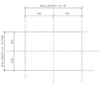
Next we’ll need to add dimensions to constrain the reference planes and then add shared parameters to control the reference planes so from the ANNOTATE ribbon, on the DIMENSION panel click ALIGNED.  Select the left reference plane, then the middle and finally the right reference plan.  Click EQ to make the reference planes equidistant.  Then create a second dimension string this time selecting only the left and right reference planes.  Repeat the process for the horizontal reference planes.


Step 4 – Creating an extrusion

With the reference planes dimensioned and constrained, it’s time to create a simple extrusion.  On the CREATE ribbon, find the FORMS panel and click EXTRUSION.  Notice there are 5 different types of forms you can create: Extrusion, Blend, Revolve, Sweep and Swept Blend.  For this exercise we’ll be using the simple extrusion form.

After clicking EXTRUSION, you will then be placed into sketch mode.  Select the RECTANGLE button and pick two points to create a rectangular shape for our simple box extrusion.  The exact placement doesn’t matter because we’ll be constraining the geometry to the reference planes, but place it within the reference planes.


Click the green check mark to complete the sketch and exit sketch mode.

Step 5 – Constraining the extrusion

Now that the extrusion is created, we need to constrain it to the outer-most reference planes.  The simplest and fastest way to do this is to use the ALIGN command.  Start the align command and select the top reference plane then select the top edge of the extrusion.  After the edge of the extrusion is aligned to the reference plane, click the padlock icon to lock the edge of the extrusion to the reference plane.  Repeat this for the remaining 3 sides of the extrusion.

Step 6 – Adding Shared Parameters

Select the overall horizontal dimension string and from the Options Bar select ADD PARAMETER from the LABEL drop-down.

The PARAMETER PROPERTIES dialog appears.  Select SHARED PARAMETER [1], click SELECT [2], select the 00_COMMON [3] category from the SHARED PARAMETERS dialog box, select BVH_LENGTH [4], click OK [5], choose whether this parameter should be a TYPE or INSTANCE [6], select which category you want the parameter to appear under in the Properties palette (you can simply use the default value) [7] (for this exercise, select the INSTANCE option so you can change the values on a per-instance basis), click OK [8].  Repeat this process for the vertical dimension string and use the BVH_WIDTH parameter.

After applying the shared parameters, the dimension strings should look like the ones below.

Now switch to an elevation view and repeat steps 2, 3, 5 & 6 to create a reference plane, dimension and add a parameter to control the depth of the cube.
When you load your new custom box family into a project and place a few instances of it, you can control the dimensions of each instance separately.  If you had selected the TYPE property for the shared parameters, you would only be able to control the dimensions of the box from the family’s
Save your new family.  Note: Depending on the complexity of the family, you may want to save it at regular intervals to avoid the risk of losing any work.

Step 7 – Flex your family

When you “flex” a family, you’re changing the values of the parameters to ensure it reacts the way you expect it to.  In some instances, you may see the dimension strings and reference planes change, but the geometry doesn’t move.  That’s because the geometry isn’t locked to the reference planes.  In a simple family such as the one we just created, not much can go wrong, but if something does go wrong, it’s rather easy to fix.
Flexing a family prior to using it becomes more critical when you have more complicated geometry and/or nested families that you want to control.


CIVIL ENGINEERING ABBREVIATION


CIVIL ENGINEERING ABBREVIATION:


The common abbreviation used in civil engineering are as following:

A.A.S.H.T.O – American Association of state highway Transport Official.
A.C.I – American Concrete Institute.
A.R.E.A – American Railway Engineering Association.
A.B – Anchor  Bolt Or Asbestos Board
AC – Asphalt Concrete
A.S.C – Allowable Stress of concrete.
A.S.T.M – American society for testing materials
AC – Asbestos cement.
AE – Assistant Engineer
APM – Assistant Project Manager
B.M – Benchmark
B.M – Bending moment.
BLK – Block Work
BOQ – Bill Of Quantities
BRW – Brick Retaining Wall
BWK – Brick Work
B.O.F – Bottom Of Foundation
BHK – Bedroom, Hall, Kitchen
C.I.Pipe – Cast iron pipe.
C.I.Sheet – Corrugated Iron sheet.
CL- Centre Line
CRW – Concrete Retaining Wall
CBW – Concrete Block Wall
CIP – Cast In Place
CMU – Concrete Masonry Unit
CJ – Construction Joint
CC – Centre To Centre
CC – Cement concrete.
CE – Chief Engineer
CP – Cement plaster.
CPM – Critical path method.
CS – Comparative statement.
D – Diameter
DL – Development Length
Dia – Diameter
DIM – Dimension
D.L – Dead load.
DPC – Damp proof course.
DPR – Daily Progress Report
DRG – Drawings
DWLS – Dowels
EJ – Expansion Joint
E.L – Environmental load.
EL – Existing Load
EGL – Existing ground level.
ELCB – Earth Leak Circuit Breaker
F.M – Fineness Modulus.
Ft – Foot Or Feet
FL – Floor Level
FGL – Formation ground level.
FOC – Factor Of Safety
GL – Ground Level
GL – Ground level.
GP – Ground plane.
HFL – Highest Flood Level.
HAC – High Alumina Cement
HP – Horizontal plane.
IOM – Inter Office Memo
ISI – Indian standard institute.
JE – Junior Engineer
JST – Joist
Kg  – Kilogram.
L.L – Live load.
LW – Light  Weight
LWC – light Weight Concrete
LC – Lime concrete.
M – Meter
MM – Millimeter.
MB – Measurement book.
MCB – Miniature Circuit Breaker
MEP – Mechanical Electrical Plumbing
MFL – Maximum Flood Level
MRC – Material Receipt Challan
MT – Metric Tonnes
N – Newton
NCF – Neat cement finishing.
OPC – Ordinary Portland Cement
OGL – Original ground level.
OSR – Open Soace Reservation Area
PC – Pile Cap
PC – Precast Concrete
PCC – Plain Cement Concrete
PERT – Programme Evaluation and Review Technique.
PL – Plinth level.
PM – Project Manager
PO – Purchase Order
PPE – Personal Protective Equipment
PPR – Poly Propylene Random.
PVC – Poly vinyl choloride .
PVC – Polyvinyl Chloride
PSF – Pound Per Square Foot
PSI – Pound Per Square Inch
PWD – Permanent Works Engineer
QC – Quality control
QS – Quantity Surveyor
RC – Reinforced Concrete
R.B.W – Reinforced brick work.
RBC – Reinforced Brick concrete.
RCC – Reinforced Cement Concrete
RMC – Ready Mixed Concrete concrete.
RL – Reduced level.
SCC – Self Compacting Concrete
STP – Sewage Treatment Plant
SRC – Sulphate Resisting Cement
SWG – Standard wire gauge.
TB – Tie Beam
TBM – Tunnel Boring Machine
TDS – Total Dissolved Solids
TOB – Top Of Beam
TMT – Thermo Mechanical Treatment
TOC – Top Of Concrete
TOW – Top Of Wall
U.S.C – Ultimate stress of concrete.
UPVC – Unplasticized Polyvinyl chloride.
USD – Ultimate strength design.
VP – Vertical plane.
W.C – Water closet.
WL – Working Level
W.S.D – Working stress Design
WO –  Work Order


Friday 20 September 2019

Remote field testing


Remote field testing

Remote field testing (RFT) is a method of nondestructive testing using low-frequency AC whose main application is finding defects in steel pipes and tubes. RFT is also referred to as remote field eddy current testing (RFEC or RFET). RFET is sometimes expanded as remote field electromagnetic technique, although a magnetic, rather than electromagnetic field is used. An RFT probe is moved down the inside of a pipe and is able to detect inside and outside defects with approximately equal sensitivity (although it can not discriminate between the two). Although RFT works in nonferromagnetic materials such as copper and brass, its sister technology eddy-current testing is preferred.
The basic RFT probe consists of an exciter coil (also known as a transmit or send coil) which sends a signal to the detector (or receive coil). The exciter coil is pumped with an AC current and emits a magnetic field. The field travels outwards from the exciter coil, through the pipe wall, and along the pipe. The detector is placed inside the pipe two to three pipe diameters away from the exciter and detects the magnetic field that has travelled back in from the outside of the pipe wall (for a total of two through-wall transits). In areas of metal loss, the field arrives at the detector with a faster travel time (greater phase) and greater signal strength (amplitude) due to the reduced path through the steel. Hence the dominant mechanism of RFT is through-transmission.

Main features
  • commonly applied to examination of boilers, heat exchangers, cast iron pipes, and pipelines.
  • no need for direct contact with the pipe wall
  • probe travel speed around 30 cm/s (1 foot per second), usually slower in pipes greater than 3 inch diameter.
  • less sensitive to probe wobble than conventional eddy current testing (its sister technology for nonferromagnetic materials)
  • because the field travels on the outside of the pipe, RFT shows reduced accuracy and sensitivity at conductive and magnetic objects on or near the outside of the pipe, such as attachments or tube support plates.
  • two coils generally create two signals from one small defect
The main differences between RFT and conventional eddy-current testing (ECT) is in the coil-to-coil spacing. The RFT probe has widely spaced coils to pick up the through-transmission field. The typical ECT probe has coils or coil sets that create a field and measure the response within a small area, close to the object being tested.


Wednesday 4 September 2019

AC Generator (Alternator)


AC Generator (Alternator) - Construction and Working


An alternator is an electrical machine which converts mechanical energy into alternating electric energy. They are also known as synchronous generators.


How Does An AC Generator Work?

The working principle of an alternator or AC generator is similar to the basic working principle of a DC generator.


Above figure helps you understanding how an alternator or AC generator works.  According to the Faraday's law of electromagnetic induction, whenever a conductor moves in a magnetic field EMF gets induced across the conductor. If the close path is provided to the conductor, induced emf causes current to flow in the circuit.
Now, see the above figure. Let the conductor coil ABCD is placed in a magnetic field. The direction of magnetic flux will be form N pole to S pole. The coil is connected to slip rings, and the load is connected through brushes resting on the slip rings.
Now, consider the case 1 from above figure. The coil is rotating clockwise, in this case the direction of induced current can be given by Fleming's right hand rule, and it will be along A-B-C-D.
As the coil is rotating clockwise, after half of the time period, the position of the coil will be as in second case of above figure. In this case, the direction of the induced current according to Fleming's right hand rule will be along D-C-B-A. It shows that, the direction of the current changes after half of the time period that means we get an alternating current.

Construction Of AC Generator (Alternator)
                                  Salient pole type alternator

Main parts of the alternator, obviously, consist of stator and rotor. But, the unlike other machines, in most of the alternators, field exciters are rotating and the armature coil is stationary.
Stator: Unlike in DC machine stator of an alternator is not meant to serve path for magnetic flux. Instead, the stator is used for holding armature winding. The stator core is made up of lamination of steel alloys or magnetic iron, to minimize the eddy current losses.
Why Armature Winding Is Stationary In An Alternator?
  • At high voltages, it easier to insulate stationary armature winding, which may be as high as 30 kV or more.
  • The high voltage output can be directly taken out from the stationary armature. Whereas, for a rotary armature, there will be large brush contact drop at higher voltages, also the sparking at the brush surface will occur.
  • Field exciter winding is placed in rotor, and the low dc voltage can be transferred safely.
  • The armature winding can be braced well, so as to prevent deformation caused by the high centrifugal force.
Rotor:  There are two types of rotor used in an AC generator / alternator:
(i) Salient and (ii) Cylindrical type
  1. Salient pole type: Salient pole type rotor is used in low and medium speed alternators. Construction of AC generator of salient pole type rotor is shown in the figure above. This type of rotor consists of large number of projected poles (called salient poles), bolted on a magnetic wheel. These poles are also laminated to minimize the eddy current losses. Alternators featuring this type of rotor are large in diameters and short in axial length.
  2. Cylindrical type: Cylindrical type rotors are used in high speed alternators, especially in turbo alternators. This type of rotor consists of a smooth and solid steel cylinder havingg slots along its outer periphery. Field windings are placed in these slots.
The DC suppy is given to the rotor winding through the slip rings and and brushes arrangement.