Busbar Trunking System (BBT) in electrical construction, uses to transporting electrical power
to a shorter distance but many utilization point, say, within the building or a
compound of facilities. Though cables can also be used in these areas, their
economic impact would be high if compared to the effective Busbar
Trunking System. It will help us to tap power directly from where we want
it to be and make utilize to the service point.
Busbar Trunking System, a prefabricated trunk
consisting of Copper / Aluminium busbars and suitable insulating medium. The
size of the trunking system will be bigger for air insulated system compared to
Sandwich type insulated Trunking system. A sample MEP specification of Busbar
Trunking System is given here for the reference.
ELECTRICAL
BUSBAR TRUNKING SYSTEM
Construction and installation of Busbar Trunking (BBT) system included:
- Comply with the General Conditions,
Supplementary Conditions and the requirements of concerned divisions /
sections of the Electrical Specification. In addition read and conform to
all Electrical Sections of these specifications.
- Provide all labour, materials, products,
equipment and services to supply and install the bus duct (busbar
trunking) as indicated on the drawings and specified in these
specifications.
REFERENCE STANDARDS FOR ELECTRICAL BUSBAR TRUNKING
SYSTEM

- All electrical installations shall be carried
out in accordance with the best International Standards and Codes of
Practice specifically with the current issue of the IEE Regulations (BS
7671) and the requirements of the supply authority.
- The entire installation shall be carried out
and tested in accordance with the relevant National and International
Standards and requirements of local authority.
- The design, manufacture, testing and
performance of the busbar trunking system shall be in accordance with the
latest edition of BSEN60439 – 1 & 2 (IEC 439 – 1 & 2) standard,
BS5486-2 and AS 3439.2.
- Types and size of Busbar Trunking required for
this project shall be in satisfactory service under similar conditions for
not less than 5 years.
- Provide verification certificates prior to
manufacturer for MEP Consultants review.
- The Busbar Trunking manufacturer shall be
certified to the highest Quality Management System Standard, namely ISO
9001 and ISO 14001 for Environmental Management Systems.
- All busbar trunking shall include a CE MARK on
its labels in accordance with the low voltage directive number 73/23/EEC
APPROVALS FOR ELECTRICAL BUSBAR TRUNKING SYSTEM
1. Do not commence
final fabrication or erection of equipment until receipt of: Reviewed or
reviewed as noted shop drawings from MEP Consultant.
2. The following tests
shall be carried out by the manufacturer on each piece of busbar trunking
before it leaves the factory: 3.5kV Dielectric Test for 4 seconds; 1000V Megger
Test.
3. A Factory
Certificate of Testing and Inspection shall be submitted to the Engineer for
review.
4. Before installation
each piece of busbar trunking shall be Megger tested at 1000V.
5. On completion of
the installation each busbar run shall be Megger tested at 1000V
6. A temperature heat
rise test in accordance with the manufacturer's recommendation/ procedure shall
be carried out on site.
7. All test results
shall be recorded and submitted to the Engineer for review.
8. The contractor
shall carry out infra-red / thermal graphic scanning of the busbar systems and
all test results shall be recorded and submitted to the engineer for review.
9. The scanning shall
be carried out under load conditions prior to handover.
10. In addition the
contractor shall allow for the scans to be repeated at the 'end of defects
liability period' and a conditional report issued to the engineer for
review. Scanning shall be carried out at switchpanel terminations,
changes of direction and on 10% of trunking joints.
COORDINATION FOR ELECTRICAL BUSBAR TRUNKING SYSTEM

- The contractor shall ensure detailed
co-ordination of installation and compatibility of busbar trunking,
transformers and switchgear as appropriate.
- Connections to switchgear shall be with
flanged end units and connections to transformers shall be with flanged
end units, transformer box and flexibles, shall be of specific design and
manufactured by the busbar trunking manufacturer.
- The contractor shall check and confirm
structural penetrations through slabs and walls with the structural
engineer prior to concrete pours or wall construction.
- In conjunction with the main contractor the
MEP contractor shall co-ordinate the provision of 100mm high concrete curb
at each opening where busbars rise through floor slabs.
- The contractor shall ensure the rising
busbars, cable tray, distribution boards, tap-off arrangement and other
services are co-ordinated in the riser space prior to installation.
- Busbar layouts indicated in the drawings are
based on dimensions of a generic nature. The contractor shall
include for ensuring the selected busbar system can be installed in all
locations without increase to room size or encroachment to other areas.
- The contractor shall carry out all necessary
site measurements to ensure the busbar system is compatible with site
dimensions and conditions.
- Confirm installed weight of busbar trunking
with structural engineer.

PRODUCTS -
ELECTRICAL BUSBAR TRUNKING SYSTEM
The contractor shall supply, install, test and commission the busbar
trunking system including flanges, elbows, tap-off boxes, supports etc.,
of the type and size as indicated in the drawings and locations designated on
the drawings. All busbar and associated installation shall be in
accordance with the following requirements. The busbar shall carry its rated
current without exceeding the temperature rise of 55ºC over an ambient of 50ºC
at 90% relative humidity in any plane without de-rating and without effecting
the local power supply requirements.
STORAGE OF ELECTRICAL BUSBAR TRUNKING SYSTEM
Store bus duct at site continuously in warm dry locations. Bus
bars or bus duct will be rejected if they have been roughly handled, or marked
at joints or connection points, or plating is damaged in any way. Do not
install bus duct until that portion of the building is enclosed and dry.
CONSTRUCTION OF BUSBAR TRUNKING
- The busbars shall be totally enclosed in a
non-ventilated, low impedance sandwich design. The busbar trunking shall
be sandwiched throughout it’s entire length, busbar trunking flared at
tap-points are not acceptable.
- The enclosure shall comprise a non-magnetic
aluminium housing with minimum metal thickness of 5mm top and bottom and
3mm sides. The aluminium housing shall be unpainted natural finish
and fully fault rated and provide additional protection by ASTA certified
integral earthing (PE protective conductor).
- Each piece of busbar trunking shall be
labelled E, L1, L2, L3, N at both ends to identify conductor phasing.
- Minimum enclosure protection shall be IP54 as
defined in BSEN 60529 and must be ASTA certified in both horizontal and
vertical positions.
- Copies of ASTA certificates for enclosure PE
short-circuit and IP ratings shall be submitted to the Engineer for
approval.
- All horizontal runs of the busbar trunking
shall be designed for IP65 operation and IP54 for the vertical runs within
risers.
RATINGS OF ELECTRICAL BUSBAR TRUNKING SYSTEM - 800A
1. The busbar trunking
shall be designed and constructed for use on a 400/415V, three phase, four
wire, 50Hz system. The minimum rated insulation voltage shall be 1000V.
Each rating of busbar trunking shall be ASTA type tested and certified for
short circuit ratings for one second covering phase, neutral, earth conductor
and the housing as an additional protective conductor.
2. Copies of ASTA test
certificates shall be provided to the engineer for each rating for review.
3. The minimum
certified short circuit ratings of the busbar trunking shall be: 800A Rating,
35kA/1Sec, 74kA Peak 21kA N&PE
 BUSBAR CONDUCTORS
- The phase and neutral busbar conductors shall
be of rectangular section made of hard drawn high conductivity copper of
99.9% purity to BSEN13601: 2002, Cu-ETP, CW004A. A Declaration of
Conformity from the copper supplier must be submitted to the Engineer.
- The neutral conductor shall be full rated,
internal earth conductor shall be half rated and be of the same material
as the phase busbars.
- The entire conductors and joint lengths shall
be tinned. All busbar conductors shall be totally enclosed in Class B130ºC
insulating polyester film material.
- An option for rating the bus bar neutral
conductor at 200% rating shall be available and the contractor shall
submit an optional cost with his tender offer.
BUSBAR TRUNKING SUPPORT
- The busbar trunking shall be properly aligned,
and securely fixed, not exceeding 1.5m (or as recommended by the
manufacturer) centres with support adequate to take the weight of the
busbar by means of galvanized fixing brackets; comprising hanger clamp,
fixing channel and damping screw, supplied by the busbar trunking
manufacturer. Additional supports shall be supplied where required and
where recommended by the trunking manufacturer.
- In vertical runs, busbars shall be designed to
allow each section of trunking to be removed on one floor only without the
need to dismantle the trunking on other floors.
BUSBAR CONDUCTOR JOINTS
- Joining of the busbar lengths shall be by
means of a quick make non-reversible joint pack comprising a double
headed, torque indicating single joint bolt, including a high visibility
disc for visual indication of unmade joints. For ease of jointing and to minimize
installation time, joints shall have a single torque bolt only.;
- The Joints shall be of a safe asymmetrical
design to ensure correct phasing when jointing two lengths.
- It shall be possible to torque the joint using
a standard long handle wrench with a 19mm socket.
- The joints shall accommodate 15mm of thermal
expansion of conductors and housing without requiring additional expansion
joints, except at building expansions.
FIRE PROTECTION FOR BUSBAR TRUNKING
- A declaration of fire resistance for 240 minutes
minimum to ISO 834, BS 476, DIN 4102 Part 2 shall be provided by the
busbar trunking manufacturers.
- Fire rated materials shall be fitted by
the contractor to fill openings where busbar trunking passes through
floors or walls with floor/wall flanges supplied by the busbar trunking
manufacturer.
TAP-OFF POSITIONS AND TAP-OFF UNITS OF BUSBAR
TRUNKING SYSTEM
- Busbar trunking shall have tap-off positions
where shown on the drawings.
- Each tap off position shall be provided with
automatic safety shutters to shield the live busbars where the position is
not occupied with a tap off unit.
- Tap-off positions shall be non-flared and suitable
for tap-off units to be plugged on to the busbars.
- Shutters shall be activated by the insertion
of the tap-off units and will only operate if the boxes are the correct
way round.
- The plug in contact shall self align with the
busbars and plug-in openings shall provide personal protection and safety
of IP 2X when in the open position and IP54 in the closed position in
accordance with BS EN 60529.
- Within risers, plug-in tap-off positions shall
be provided with a maximum distance of one plug-in opening for each
1000mm.
- Tap-off boxes shall be constructed of zinc
plated sheet steel and shall be complete with hinged lids with an ASTA
certified protective standard of IP54.
- The tap-off boxes shall have circuit
protective devices as applicable and shown on the drawings with mechanical
interlocks to prevent tap box removal unless the mechanism is in the off
position.
- Where tap-off boxes are inserted into live
busbar trunking, they shall be designed and constructed so that the
current carrying metal parts are not exposed during the insertion and
removal of the boxes.
- The tap-off box shall remain earthed during
removal, until all live connections are disabled. The tap-off box shall
ensure that the box can only be inserted to give correct polarity.
- All operational handles shall be pad lockable.
- Tap-off boxes up to 630A shall be of the
plug-on type for ease of installation and removal.
- The tap-off units shall be MCCB current
limiting type. The MCCBs shall complement those used elsewhere (for the
distribution panels) in order to allow co-ordination and future addition
of shunt trip/motor operation devices.
- Cast resin bus bar shall be utilised to
achieve the fire rating requirement where noted on the drawings and called
for in the specification (see concerned section).
- Generally the cast resin bus bars shall be as
outlined above.
- Manufacturer: Recommended in the list of
Manufacturer or equal and approved.
EXECUTION OF ELECTRICAL BUSBAR TRUNKING SYSTEM
INSTALLATION
- Installation manuals detailing handling,
storage, installation, energisation, maintenance and joint assembly must
be provided by the manufacturer. The contractor shall ensure that the
busbar trunking is stored on site in accordance with the manufacturer’s
installation manual, in a clean and dry environment.
- Provide low reactance bus duct system as
specified and shown.
- Install system as specified and shown and as
recommended by Bus Duct Manufacturer.
- Use a torque wrench to ensure uniform tension
on bus duct joints. After completion of installation and before
system is turned over to Owners, re-check each bolted joint with a torque
wrench in an approved manner. Torque adjustment shall be as recommended
by Bus Duct Manufacturer.
- Cover ventilated bus with a weather proof
heavy duty plastic envelope as soon as it has been installed. Do not
remove this cover until the building is clean and dry and bus ready to
megger and energise.
- Megger each bus duct in an approved manner
before it is energised.
- Bus duct layout throughout has been based on
dimensions of a generic bus duct. The Contractor shall include for
ensuring that the bus duct selected can be installed in locations
indicated without any increase in contract price and without any increase
to room size or encroachment of other areas.
- Ensure that adequate spacial provision and/or
allowance is made for pouring resin compound when making joints on cast
resin busbar.
- Ensure the rising busbars, cable tray,
distribution board, tap off arrangement and other services are coordinated
in the riser spaces prior to installation.
- Provide protective sleeves around bus ducts as
they pass through walls and floors prior to making good.

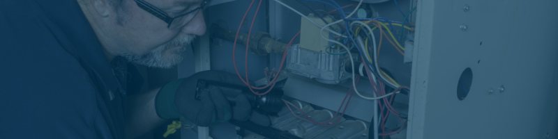
 In
the past, we have discussed the importance of having
your air ducts cleaned on a regular basis. However, most homeowners
believe that their homes are clean enough that they don’t have to worry. You
may be shocked to learn just how many harmful contaminants gather inside of
your air ducts, even without you noticing them! Here are some of the biggest
threats hiding in your HVAC system.
In
the past, we have discussed the importance of having
your air ducts cleaned on a regular basis. However, most homeowners
believe that their homes are clean enough that they don’t have to worry. You
may be shocked to learn just how many harmful contaminants gather inside of
your air ducts, even without you noticing them! Here are some of the biggest
threats hiding in your HVAC system.
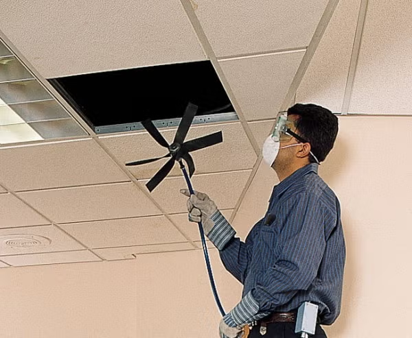
 Homeowners should
be especially aware of inanimate particles in their HVAC system if they have
been doing any work on their homes. These include:
· Drywall Dust
Homeowners should
be especially aware of inanimate particles in their HVAC system if they have
been doing any work on their homes. These include:
· Drywall Dust

 In general, experts
recommend having your air ducts cleaned every other year to prevent excessive build
up in your system. Also, you should have your ducts cleaned anytime there has
been a water leak or a construction project that may have caused build up to
accumulate faster than usual. If you feel like you are always dusting, or your
allergies are getting consistently worse with time, having your air ducts cleaned is a good place to start. Even if it is not the only culprit, it
can still provide notable improvements in your health. If you are noticing a
moldy or mildew smell settling in your house, make sure you call right away
because mold spores can cause significant damage to your health and home.
In general, experts
recommend having your air ducts cleaned every other year to prevent excessive build
up in your system. Also, you should have your ducts cleaned anytime there has
been a water leak or a construction project that may have caused build up to
accumulate faster than usual. If you feel like you are always dusting, or your
allergies are getting consistently worse with time, having your air ducts cleaned is a good place to start. Even if it is not the only culprit, it
can still provide notable improvements in your health. If you are noticing a
moldy or mildew smell settling in your house, make sure you call right away
because mold spores can cause significant damage to your health and home.
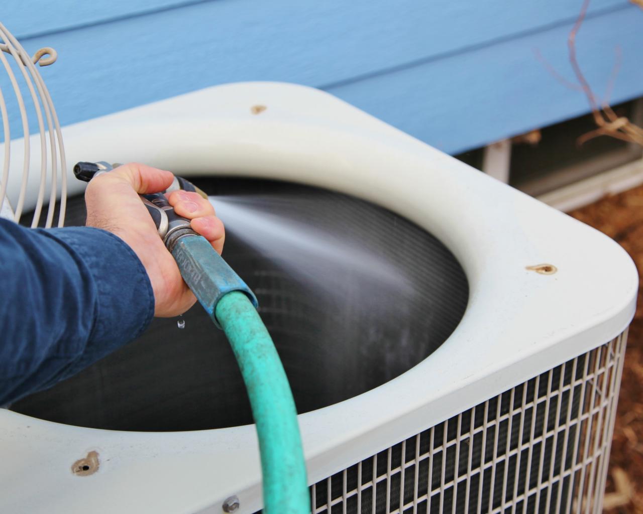
 Water leaks in your
ducts could be introducing outside particles into the system and make things
even worse. Your ducts should be properly sealed and cleaned to keep your air
conditioner in excellent shape year round.
Water leaks in your
ducts could be introducing outside particles into the system and make things
even worse. Your ducts should be properly sealed and cleaned to keep your air
conditioner in excellent shape year round.