CREATING A SIMPLE REVIT FAMILY
In this first entry, we’ll run through the steps to create a simple parametric box using reference planes, dimensions and constraints, shared parameters to control the length, width and depth of the box and we’ll wrap up by creating a type catalog for our new family.
Step 1 – Creating a new family
Start by creating a new family using the GENERIC MODEL.RFT file. Note the file extension: RFT is
a Revit family template. RFA files are the actual Revit family.
Step 2 –
Adding Reference Planes
 Reference planes are 2-dimensional
guidelines used to control the 3D geometry of the family. To create
reference planes, from the CREATE ribbon, on the DATUM panel click REFERNECE
PLANE (or type RP). Now draw four reference planes in a clock-wise
manner. Don’t worry about their spacing. We’ll fix that in the next
step using dimensions to constrain the reference planes.
Step 3 –
Adding dimensions, constraints and shared parameters
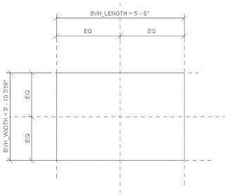
Next we’ll need to add dimensions to
constrain the reference planes and then add shared parameters to control the
reference planes so from the ANNOTATE ribbon, on the DIMENSION panel click
ALIGNED. Select the left reference plane, then the middle and finally the
right reference plan. Click EQ to make the reference planes equidistant.
Then create a second dimension string this time selecting only the left and
right reference planes. Repeat the process for the horizontal reference
planes.
Step 4 –
Creating an extrusion
With the reference planes dimensioned
and constrained, it’s time to create a simple extrusion. On the CREATE
ribbon, find the FORMS panel and click EXTRUSION. Notice there are 5
different types of forms you can create: Extrusion, Blend, Revolve,
Sweep and Swept Blend. For this exercise we’ll be using the simple
extrusion form.
After clicking EXTRUSION, you
will then be placed into sketch mode. Select the RECTANGLE button and
pick two points to create a rectangular shape for our simple box
extrusion. The exact placement doesn’t matter because we’ll be constraining
the geometry to the reference planes, but place it within the reference planes.
Click the green check mark to complete
the sketch and exit sketch mode.
Step 5 –
Constraining the extrusion
Now that the extrusion is created, we
need to constrain it to the outer-most reference planes. The simplest and
fastest way to do this is to use the ALIGN command. Start the align
command and select the top reference plane then select the top edge of the
extrusion. After the edge of the extrusion is aligned to the reference
plane, click the padlock icon to lock the edge of the extrusion to the
reference plane. Repeat this for the remaining 3 sides of the extrusion.
Step 6 –
Adding Shared Parameters
Select the overall horizontal
dimension string and from the Options Bar select ADD PARAMETER from the LABEL
drop-down.
The PARAMETER PROPERTIES dialog
appears. Select SHARED PARAMETER [1], click SELECT [2], select the
00_COMMON [3] category from the SHARED PARAMETERS dialog box, select
BVH_LENGTH [4], click OK [5], choose whether this parameter should be a TYPE or
INSTANCE [6], select which category you want the parameter to appear under in
the Properties palette (you can simply use the default value) [7] (for this
exercise, select the INSTANCE option so you can change the values on a
per-instance basis), click OK [8]. Repeat this process for the vertical
dimension string and use the BVH_WIDTH parameter.
After applying the shared parameters,
the dimension strings should look like the ones below.
Now switch to an elevation view and
repeat steps 2, 3, 5 & 6 to create a reference plane, dimension and add a
parameter to control the depth of the cube.
 When you load your new custom box
family into a project and place a few instances of it, you can control the
dimensions of each instance separately. If you had selected the TYPE
property for the shared parameters, you would only be able to control the
dimensions of the box from the family’s
Save your new family. Note:
Depending on the complexity of the family, you may want to save it at regular
intervals to avoid the risk of losing any work.
Step 7 –
Flex your family
When you “flex” a family, you’re
changing the values of the parameters to ensure it reacts the way you expect it
to. In some instances, you may see the dimension strings and reference
planes change, but the geometry doesn’t move. That’s because the geometry
isn’t locked to the reference planes. In a simple family such as the one
we just created, not much can go wrong, but if something does go wrong, it’s
rather easy to fix.
Flexing a family prior to using it
becomes more critical when you have more complicated geometry and/or nested
families that you want to control.


No comments:
Post a Comment