12
TIPS TO MASTER REVIT DOOR
1- UNDERSTAND
WHAT TO MODEL AND WHAT TO NEST
 To
properly organize your Revit door family, make sure to understand which part
should be modeled directly in the main door family, and which part should be
loaded as a nested family. For those without programming experience: a nested
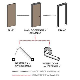
family means a family inside a family. Take a look at this chart:
This is an optimal workflow for
beginners and intermediate users. Model the door panel and frame directly in
the main door family. Use nested families for the plan swing and for any
hardware components like handles.
This technique has an exception: if
you are an advanced user with a large library of panels and frames, it can be a
good idea to use nested families for everything. In this advanced strategy, the
main door family is only used to contain all the nested families
2- PLAN THE DOOR
YOU WANT TO CREATE
Before creating the family, make sure
you understand what kind of door family you want to create. Here is the kind of
information you need to know:
- Will you be using a steel frame or
a wood frame?
- Is it a simple door or a double
door?
- Do you want a trim around the door
opening?
- Are you going to use the door for
3D views and renderings? If so, you will need to think about hardware families
for more realism.
- Are you creating a door with a
simple solid panel, or with a multiple panels and glazing?
- What dimensions to you want to be
able to customize apart from the width and height of the door?
Draw a sketch of the door you need.
Start to plan which parameters and reference planes you will have to create.
When you are ready, create a new door
family using the standard Autodesk door family template.
3- USE
EXTRUSION TO MODEL DOOR PANELS
Most
door panels should be modeled using the Extrusion tool. Use the “Pick Lines”
Drawing option. Go to an elevation and lock the boundary lines to the reference
planes.
Then, assign the door thickness in plan view. Create a new
reference plane and assign a “Thickness” dimension. Align the door panel to the
new reference plane and lock.
4- SET UP THE
“ROUGH” DIMENSIONS
Sometimes, you might want to know the
total wall opening dimension, which might be different from the door panel when
you include the frame. That is when the Rough Width and Rough Height
dimensions become useful.
Usually,
the rough dimensions are found by adding the door Height and Width to the frame
thickness. You might also want to subtract a value to account for the overlap
between the frame and the wall. In the example below, we created a formula to
automatically calculate Rough Width and Rough Height values. We consider there
is an wall/frame overlap of 19mm. If you modify the Frame Thickness, the Height
or the Width, the rough dimensions will automatically be updated.
The
door Opening Cut is usually created in relation to the rough dimensions. In the
door elevation, make sure to lock the Opening Cut to reference planes that are
associated to the “Rough Width” and “Rough Height”


No comments:
Post a Comment