Saturday, 7 October 2017

Robotic Farm Completes 1st Fully Autonomous Harvest


Hands Free Hectare is an experimental farm run by researchers from Harper Adams University, in the United Kingdom.


It's harvest season in many parts of the world, but on one farm in the United Kingdom, robots — not humans — are doing all the heavy lifting. 
At Hands Free Hectare, an experimental farm run by researchers from Harper Adams University, in the village of Edgmond in the U.K., about 5 tons (4.5 metric tons) of spring barley have been harvested from the world’s first robotically tended farm. Everything from start to finish — including sowing, fertilizing, collecting samples and harvesting — has been done by autonomous vehicles on the farm, according to the researchers.
The team behind the project thinks that robotic technology could improve yields in agriculture, which is necessary if the world's growing population is to be fed in coming years.
The researchers tackled this problem by using commercially available agriculture machines and open-source software that is used to guide hobbyists’ drones.
"In agriculture, nobody has really managed to solve the problem of autonomy," said Jonathan Gill, mechatronics researcher at Harper Adams University, who led the project."We were like, Why is this not possible? If it's possible in drone autopilots that are relatively cheap, how come there are companies out there that are charging exorbitant amounts of money to actually have a system that just follows a straight line?"
The researchers purchased several small-size agricultural machines, including a tractor and a combine, a machine for harvesting grain crops. They then fitted the machines with actuators, electronics and robotic technology that would allow them to control the machines without the presence of a human operator.
"The first stage was to make it radio controlled," Gill said. "This was our first step towards autonomy. From that point, we moved on to preprogram all the actions that need to be performed into the autopilot system."
Gill's collaborator, Martin Abell, who works for Precision Decisions, an industrial agricultural company that partners with the university, explained that the system follows a certain trajectory with preprogrammed stops to perform certain actions.
"The vehicles navigate entirely based on the GPS, and they are just essentially driving towards targets that we predetermined," Abell said. "At different GPS targets, there are different actions designed to be carried out."
Abell said the researchers struggled to make the machines follow a straight line, which initially resulted in quite a lot of crop damage. However, the scientists think they will be able to fix the problem in the coming years and will eventually achieve better yields than a conventionally maintained farm of the same size could produce.
To monitor the field and take samples of the plants, the researchers developed special grippers attached to drones. As the drone flies above the field, the grippers can cut off some samples and deliver them to the researchers.
The scientists said that the robotic technology could enable future farmers to more precisely distribute fertilizers and herbicides, but could also lead to improvements in soil quality. Currently, to achieve all the required tasks in a reasonable amount of time, farmers rely on very large and heavy machines. In the future, they could use flocks of smaller robotic tractors and harvesters, the researchers said.
The farmer would, for example, be able to apply fertilizer only to the plants that are doing poorly and wouldn’t waste it on those that don't need it, the researchers explained.
"At the moment, the machines used in agriculture are large, they operate quickly, they cover large areas of ground quickly, but with it comes inaccuracy," Abell said. "Small machines working with smaller working widths would provide a means to bring the resolution down. Instead of a 100-foot (30 meters) sprayer, you would have a 20-foot (6 m) sprayer, and that’s just the beginning of making things smaller."
The Harper Adams team plans to use the robotically harvested spring barley to make a limited batch of "hands-free" beer that will be distributed to the project’s partners as a token of thanks.
In the coming years, they want to focus on improving the precision of the procedures and quantify the effects of the robotic technology on the yields.

Suits That Turn Robots into Real-Life 'Transformers'

These exoskeletons could help robots perform a variety of missions. Clockwise from the top: Glider-bot, Walk-bot, Wheel-bot & Boat-bot
Just as one might don a wet suit to work underwater or a spacesuit to work in space, researchers are designing exoskeletons for robots so the machines can wear a variety of outfits tailored to different missions.
In experiments, self-folding, heat-activated origami suits created for robots could help the machines walk, roll, sail and glide, according to the new study.
"Imagine future applications for space exploration, where you could send a single robot with a stack of exoskeletons to Mars," study co-author Shuguang Li, a postdoctoral fellow at MIT's Computer Science and Artificial Intelligence Laboratory, said in a statement"The robot could then perform different tasks by wearing different outfits."
Unlike the shape-shifting robots in the "Transformers" films, in real life, existing bots are typically much less adaptable. Each part of a robot usually has a fixed structure and a single, defined purpose, making it difficult for robots to perform a wide variety of actions, the researchers said.
In contrast, animals can often change their shapes to adapt to their environments. For instance, caterpillars undergo metamorphosis to become butterflies, and hermit crabs can switch their shells.
The scientists drew inspiration from nature to develop a robot that could transform itself with different outfits that enable it to perform different tasks.
"If we want robots to help us do things, it's not very efficient to have a different one for each task," study senior author Daniela Rus, director of MIT's Computer Science and Artificial Intelligence Laboratory, said in a statement. "With this metamorphosis-inspired approach, we can extend the capabilities of a single robot by giving it different accessories to use in different situations."
The researchers used a small magnetic cube that they called "Primer." They placed the cube in an arena where they could use magnetic fields to make Primer move like a robot.
In experiments, the scientists had Primer move onto various plastic origami sheets mounted on hot plates. Turning on the hot plates could then make the heat-activated sheets fold around the cube into various shapes in roughly 3 minutes.
Each of the exoskeletons Primer could wear had its own advantages. For example, "Wheel-bot" had wheels that helped it to move twice as fast as "Walk-bot." "Boat-bot" could float on water and carry nearly twice its weight. And "Glider-bot" could soar through the air.
Primer can even don multiple outfits at once, like a Russian nesting doll, according to the study. It could add one exoskeleton to become "Walk-bot," and then interface with another, larger suit that allows it to carry objects and move two body lengths per second. After Primer was finished with a task, it could step into water to dissolve any exoskeleton the device wore in less than 1 minute, the researchers said.
Now that the scientists have shown that Primer can wear a variety of exoskeletons, future research could show that similar suits could be developed for motorized robots as well, said study lead author Shuhei Miyashita, director of the microrobotics group at the University of York, in England. Potential applications could include ingestible robots that could use several exoskeletons to perform a number of tasks in the body, such as removing objects and patching wounds, he said.
Future research will also aim to create even more functional exoskeletons, to perform tasks ranging "from burrowing in sand to driving through water," Miyashita told Live Science. The scientists would also like "to make these robots smaller and more intelligent, and potentially use different types of biomaterials" so they can perform long-term operations in the body, he said.
Miyashita and his colleaguesdetailed their findings online Sept. 27 in the journal Science Robotics.

Saturday, 23 September 2017

HYPERBARIC WELDING

Hyperbaric welding


Hyperbaric welding is the process of welding at elevated pressures,normally underwater.Hyperbaric welding can either take place wet in the water itself or dry inside a specially constructed positive pressure enclouser and hence a dry environment. It is predominantly referred to as hyperbaric welding when used in a dry environment, and underwater welding when in a wet environment. The applications of hyperbaric welding are diverse it is often used to repair ships, offshore oil platforms, and pipelines. Steel is the most common material welded.
Dry welding is used in preference to wet underwater welding when high quality welds are required because of the increased control over conditions which can be exerted, such as through application of prior and post weld heat treatments. This improved environmental control leads directly to improved process performance and a generally much higher quality weld than a comparative wet weld. Thus, when a very high quality weld is required, dry hyperbaric welding is normally utilized. Research into using dry hyperbaric welding at depths of up to 1,000 meters (3,300 ft) is ongoing. In general, assuring the integrity of underwater welds can be difficult (but is possible using various nondestructive testing  applications), especially for wet underwater welds, because defects are difficult to detect if the defects are beneath the surface of the weld.
Underwater hyperbaric welding was invented by the Russian metallurgist Konstantin Khorenov in 1932.

Application

Welding processes have become increasingly important in almost all manufacturing industries and for structural application. Although a large number of techniques are available for welding in atmosphere, many of these techniques cannot be applied in offshore and marine application where presence of water is of major concern. In this regard, it is relevant to note that a great majority of offshore repairing and surfacing work is carried out at a relatively shallow depth, in the region intermittently covered by the water known as the splash zone. Though numerically, most ship repair and welding jobs are carried out at a shallow depth, the most technologically challenging task is repair at greater depths, especially in pipelines and repair of accidental failure. The advantages of underwater welding are largely of an economic nature, because underwater-welding for marine maintenance and repair jobs bypasses the need to pull the structure out of the sea and saves valuable time and dry docking costs. It is also an important technique for emergency repairs which allow the damaged structure to be safely transported to dry facilities for permanent repair or scrapping. Underwater welding is applied in both inland and offshore environments, though seasonal weather inhibits offshore underwater welding during winter. In either location, surface supplied air is the most common diving method for underwater welders

Dry welding

Dry hyperbaric welding involves the weld being performed at raised pressure  in a chamber filled with a gas mixture sealed around the structure being welded.
Most arc welding processes such as Shielded Metal Arc Welding (SMAW), Flux-cored arc welding(FCAW), Gas tungsten arc welding (GTAW), Gas metal arc welding (GMAW), Plasma Arc Welding (PAW) could be operated at hyperbaric pressures, but all suffer as the pressure increases. Gas tungsten arc welding is most commonly used. The degradation is associated with physical changes of the arc behaviour as the gas flow regime around the arc changes and the arc roots contract and become more mobile. Of note is a dramatic increase in arc voltage which is associated with the increase in pressure. Overall a degradation in capability and efficiency results as the pressure increases.
Special control techniques have been applied which have allowed welding down to 2,500 m (8,200 ft) simulated water depth in the laboratory, but dry hyperbaric welding has thus far been limited operationally to less than 400 m (1,300 ft) water depth by the physiological capability of divers to operate the welding equipment at high pressures and practical considerations concerning construction of an automated pressure / welding chamber at depth.


Wet Welding

Wet underwater welding directly exposes the diver and electrode to the water and surrounding elements. Divers usually use around 300–400 amps of direct current to power their electrode, and they weld using varied forms of arc welding This practice commonly uses a variation of shielded metal arc welding, employing a waterproof  electrode Other processes that are used include flux-cored arc welding and friction welding  In each of these cases, the welding power supply  is connected to the welding equipment through cables and hoses. The process is generally limited to low carbon equivalent steels especially at greater depths, because of hydrogen-caused cracking
Wet welding with a stick electrode is done with similar equipment to that used for dry welding, but the electrode holders are designed for water cooling and are more heavily insulated. They will overheat if used out of the water. A constant current welding machine is used for manual metal arc welding. Direct current is used, and a heavy duty isolation switch is installed in the welding cable at the surface control position, so that the welding current can be disconnected when not in use. The welder instructs the surface operator to make and break the contact as required during the procedure. The contacts should only be closed during actual welding, and opened at other times, particularly when changing electrodes.
The electric arc heats the work piece and the welding rod, and the molten metal is transferred through the gas bubble around the arc. The gas bubble is partly formed from decomposition of the flux coating on the electrode but it is usually contaminated to some extent by steam. Current flow induces transfer of metal droplets from the electrode to the work piece and enables positional welding by a skilled operator. Slag deposition on the weld surface helps to slow the rate of cooling, but rapid cooling is one of the biggest problems in producing a quality weld

Hazards and risks


The hazards of underwater welding include the risk of electric shock to the welder. To prevent this, the welding equipment must be adaptable to a marine environment, properly insulated and the welding current must be controlled. Commercial divers must also consider the occupational safety issues that divers face; most notably, the risk of decompression sickness due to the increased pressure of breathing gases  Many divers have reported a metallic taste that is related to the galvanic breakdown of dental amalgam  There may also be long term cognitive and possibly musculo skeletal effects associated with underwater welding.


ROBOTIC APPLICATION IN NDT

The Use of Industrial Robots for NDT Applications 

The Use of Industrial Robots for NDT Applications


Nondestructive testing is the preferred quality control technique for many manufacturers from different domains ranging from industrial to aerospace. With automated NDT, we use scanners and robots to increase the speed and repeatability factor of NDT techniques,creating

much more efficiently produced precision measurements. However, obvious automated NDT scanner requirements are needed to achieve high quality control and precision measurements.

This article provides a basic comparison between typical Cartesian scanners using a combination of linear axes (X, Y and Z axes) and rotational axes, and articulated robotic arm systems using six polar axes, often used for handling machine tools, welding and part movement. 


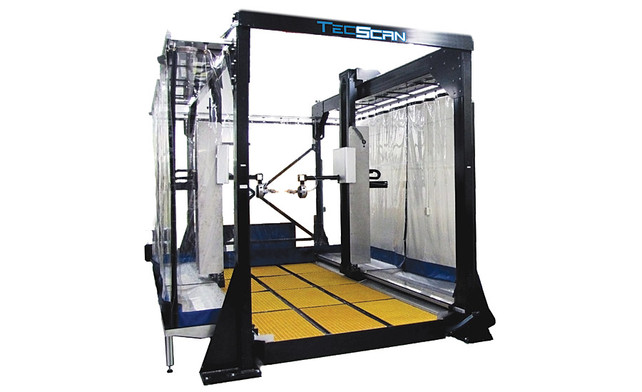
 AUTOMATED CARTESIAN SCANNERS

Typical scanners in the NDT industry consist of Cartesian scanners that can be customized for their respective job specifications. These systems are usually designed with highly accurate actuators, servo or stepper motors and optical encoder modules, making them ideal tools for real-time signal acquisition during the axes movement. They also provide automation with increased inspection speed, real-time signal processing, imaging capabilities and scanning repeatability. However, in order to achieve such design characteristics, stringent requirements must be imposed on the scanner’s automation technology being used. Some of these requirements consist of: the mechanical design for high positioning accuracy of all axes; the motion control strategy designed for fast position feedback; the required real-time encoder monitoring; the integration of high-speed interface for fast data transfer rate. 
Whether using scanners for automated ultrasonic or eddy current testing, the quality of the scanner is related to the final results of C-scan mapping, which are directly related to the signal acquisition and probe’s position and stability during said acquisition. This becomes even more critical when dealing with parts exhibiting complex 3D geometries. An additional challenge exists in designing automated scanners with increased dexterity for handling common complex geometries. The Cartesian scanner solution then becomes a multi-axis scanner where the position of all axes needs to be synchronized to achieve accurate testing. Although the ultimate aim of automated NDT is to achieve speed and carry out total inspection, when performing scanning of critical components such as for the aerospace industry, inspection reliability, resolution and repeatability become more important than the overall inspection time.


The reliable positional accuracy and repeatability performances of such scanners are usually obtained from good metrological alignment conditions. Once these scanners are designed with enough axes, they can reach any inspection point in 3D space and follow the inspected part curvature. In addition, when using an advanced motion control system, Cartesian scanners can be extremely precise and capable of accurately and reliability scanning complex surfaces with relatively high speeds.

ARTICULATED ARM ROBOTS
Industrial robotic arms present precise articulated mechanical links whose functions are similar to a human arm. Their links are jointed to provide rotational motions and manipulate objects within a certain volume. Off the shelf industrial robots are recognized as a polyvalent and robust solution for many applications: welding, palletizing, material handling, machine tending, laser cutting, machining, etc.
Compared to typical Cartesian gantry systems, the concept of an articulated arm provides a system with greater dexterity. Such robots can help advanced NDT methods if they meet the basic standards of automated NDT testing: data acquisition, repeatability, accuracy and precision.

MOTION CONTROL
The important complication of using robotic arms for automated NDT is the proprietary motion controller design that these robot use. With such control, we are locked into proprietary programs and limited motion control capabilities.
More specifically, we have limited control and not enough information of the robot positions when it moves from one point to another. Automated NDT systems require acquiring data on the fly while the robotic arm is moving. Therefore, the motion control system needs to handle extremely fast control changes (fast PID controller loops). For example, in applications that require the robot to move fast and perform contour following motions around a complex surface, smooth and precise trajectories must be maintained during the robot movement. When the PID loops close at a slow pace, the robot will not move on required precise trajectories. This can results in a jumpy motion of the robot and losses of the NDT signal measurements. Current industrial robots offer slow PID control loops, estimated around 10 times less than the required speed to perform fast and accurate NDT scanning of complex parts.
 DATA ACQUISITION
Another challenging factor for using industrial robots for NDT application is the required data acquisition speed. Capturing NDT data in real time while using a robotic arm is a challenging feat since it requires real-time robot position monitoring. This means that a direct encoder feedback has to be made available on the robot, which is generally not the case. All standard robot controllers will provide low rate of position feedback at around 200 Hz, after being processed by the motion controller unit. As the robots “true” position must be attached to each measurement point and no interpolation is allowed, the rate at which position feedback refreshes itself has a proportional impact on the inspection speed.
By working on the main challenges identified above, industrial robots can eventually replace the conventional Cartesian scanners in selected NDT application if motion control functions and encoder feedback monitoring are customized. But at this moment without such modifications in terms of the support data transfer, link and communication protocols, an efficient use of articulated robotic arms for NDT is still a work in progress