Thursday, 28 February 2019

How to obtain Building Permit in Kerala: A step-by-step guide


How to obtain Building Permit in Kerala: A step-by-step guide


A Step-by-step guide to obtain a Building Permit in Kerala

1.     Identify the Property


First of all, identify the plot where you plan to construct the building. Consult your architect and prepare a sketch that complies with the Kerala Municipality Building Rules (KMBR) or Kerala Panchayat Building Rules (KPBR) according to the jurisdiction under which your property falls.
The sketch should include the following details
·         Site layout
·         Building elevation
·         Sections
·         Site plan (plot width, setbacks, access road width)
·         Floor plan (all floors)
·         Roof or terrace plan
·         Details of septic tank and soak pit
·         Rain water harvesting
·         Location plan
An application for a building permit in Kerala should also cite details like
Site location, Whether the property is for Residential or commercial use, An Index of all drawings submitted, Number of sheets, Date, Names of Draftsman & Reviewer,  Scale, Location details including details of Village/Taluk/District, Survey number and resurvey number of the property, Ward number, Extent (in arcs and cents), Proposed building area, Plinth and carpet area of all floors, Plinth and carpet area of the car porch, Total area, Coverage, FAR (Floor Area Ratio is calculated as the ratio of the Total floor area on all floors to The Plot Area), Permit area, Joinery schedule etc.

2.     Get your documentation up-to-date

While the Architect works on Step #1, you should also get the following documentation related to the property up to date
·         Possession certificate (This is an online document)
·         Latest land tax receipts
·         Copy of the “Aadharam” or Title Deed

3.     Get online approval from the Local self-governing body

Application for a building permit can be made only by a licencee at the Local Self-governing body (Panchayat, Municipality or Corporation) under whose jurisdiction the property falls. The licencee could be an Architect, a licenced draftsman or a licenced engineer.
The documents mentioned in steps#1 and #2 above are then handed over to the licencee. The licencee then applies for an online approval for the building permit (e-filing) at the local self-governing body office.

4.     Acknowledgment from the Local self-governing body

The application has to be acknowledged by the authorities concerned at the local self governing body.

5.     Submission of the Building Permit application by a licencee

Hard copies of the following documents should be filed and submitted by the licencee.
List of documents for a Building permit application.
·         Possession certificate (This is an online document)
·         Latest land tax receipts
·         Copy of the “Aadharam” or Title Deed
·         3 copies of the Sketch or Sanction drawing
·         Copy of Architect’s or Licencee’s licence
·         Online acknowledgment certificate issued by the local self-governing body
Submit the file containing these documents at the local self-governing body. You should submit the relevant original documents also for verification. The local self-governing body office will then issue a file number for your application.

6.     Verification by the Building Inspector

The Building Inspector(BI) will then visit your property, assess the veracity of the information provided in your application and submit the report to the Assistant Engineer (AE).

7.     Verification by the Assistant Engineer

The AE will then perform another round of verification and submit the report to the Assistant Executive Engineer (AXE).

8.     Approval of the application

The AXE then approves or rejects the application. For buildings up to 350 sq. m (~3700 sq. ft.), this would suffice. However, for larger buildings there would be higher levels of scrutiny and would require further levels of approvals. This would differ from one local self-governing body to another.

9.     Fee payment and issue of Building Permit

Finally, for approved applications, you can submit the fees at the local self-governing body office. The building permit will then be issued and sent to your registered address.
To conclude
Building Permit is a mandatory documentation for constructing a building in Kerala. The procedures for obtaining the permit are now relatively simpler and easier to use.


Friday, 22 February 2019

AUTO DESK REVIT ARCHITECTURE


Auto desk Revit Architecture
Auto desk Revit Architecture is a robust architectural design and documentation software application created by Auto desk for architects and building professionals. The tools and features that make up Revit Architecture are specifically designed to support building information modelling (BIM) workflows.
Revit originally created for Charles River Software was founded in Newton, Massachusetts, on October 31, 1997, by Leonid Raiz and Irwin Jungreis, key developers of PTC's Pro/Engineer software for mechanical design, with the intent of bringing the power of parametric modelling to the building industry

Difference   between Revit and AutoCAD
Revit vs. AutoCAD. ... The main difference is that AutoCAD is primarily a drafting tool to create basic geometry that represents real life, while Revit is used to create geometry that is equipped with real-life information, hence the term building information modelling, or BIM.
Autodesk Revit is Building Information Modelling (BIM) software for Microsoft Windows, which allows the user to design with parametric modelling and drafting elements. Building Information Modelling (BIM) is a new Computer Aided Design (CAD) paradigm that allows for intelligent, 3D and parametric object-based design.


Modelling
The Revit work environment allows users to manipulate whole buildings or assemblies (in the project environment) or individual 3D shapes (in the family editor environment). Modelling tools can be used with pre-made solid objects or imported geometric models. However, Revit is not a NURBS modeller and also lacks the ability to manipulate an object's individual polygons except on some specific object types such as roofs, slabs and terrain or in the massing environment.
There are many categories of objects ('families' in Revit terminology), which divide into three groups:
·         System Families, such as walls, floors, roofs and ceilings which are built inside a project
·         Loadable Families / Components, which are built with primitives (extrusions, sweeps, etc.) separately from the project and loaded into a project for use
·         In-Place Families, which are built in-situ within a project with the same toolset as loadable components 

An experienced user can create realistic and accurate families ranging from furniture to lighting fixtures  as well as import existing models from other programs. Revit families can be created as parametric models with dimensions and properties. This lets users modify a given component by changing predefined parameters such as heightwidth or number in the case of an array. In this way a family defines a geometry which is controlled by parameters, each combination of parameters can be saved as a type, and each occurrence (instance in Revit) of a type can also contain further variations. For example, a swing door may be a Family. It may have types describing different sizes, and the actual building model will have instances of those types placed in walls where instance-based parameters could specify the door hardware uniquely for each occurrence of the door.
Due to the copyright nature of project work, it is rare and impractical to be able to buy fully 3D modeled Revit project models. Indeed, as most projects are site specific and bespoke, obtaining an existing model is in many instances unsuitable. However, there are circumstances where new practices or students that are training to learn Revit, do have a need to refer to completed models. Sources for these are limited, however they can be purchased at websites like BIMGallery and downloaded from websites like GrabCad. Revit model files have also been located using google search string "index of" + rvt" + "central" -html -htm -php
Although Revit software comes with a range of families out of the box (OOTB), they are limited, so users can find a need to build their own families or buy them from online stores such as Plansort, Bimbandit or Andekan. A number of websites offer families for free including Revit City, AUGI, BIM Object, BIMsmith and National Bim Library.
In 2011 Dynamo was released in beta form allowing first glimpses of directly programming the behaviour of hosted components through a drag and drop node interface. This is similar to the way the visual programming language Grasshopper 3d works on objects in Rhinoceros 3D.
Rendering
When a user makes a building, model, or any other kind of object in Revit, they may use Revit's rendering engine to make a more realistic image of what is otherwise a very diagrammatic model. This is accomplished by either using the premade model, wall, floor, etc., tools, or making her or his own models, walls, materials, etc. Revit 2010 comes with a plethora of predefined materials, each of which can be modified to the user's desires. The user can also begin with a "Generic" material. With this, the user can set the rotation, size, brightness, and intensity of textures, gloss maps (also known as shinemaps), transparency maps, reflection maps, oblique reflection maps, hole maps, and bump maps, as well as leaving the map part out and just using the sliders for any one (or all or none) of the aforementioned features of textures.

Cloud-based rendering with the experimental plug-in dubbed Project Neon, located on Autodesk Labs is in the beta phases and allows for the user to render their images through their Autodesk account instead of locally through their own computers. Revit models may also be linked directly into Autodesk 3ds Max (release 2013 and later) for more advanced rendering and animation projects with much of their material and object information maintained. need to modify.


Wednesday, 20 February 2019

MICRO ELECTRO MECHANICAL SYSTEM - MEMS


MICRO ELECTRO MECHANICAL SYSTEM


                                            Microelectromechanical systems (MEMS, also written as micro-electro-mechanical, Microelectromechanical or microelectronic and microelectromechanical systems and the related micro mechatronics) is the technology of microscopic devices, particularly those with moving parts. It merges at the Nano-scale into nanoelectromechanical systems (NEMS) and nanotechnology. MEMS are also referred to as micro machines in Japan, or micro systems technology (MST) in Europe.
              
                                  MEMS technology consist of microelectronic elements actuators, sensors and mechanical structures built onto a substrate which is usually “Silicon”. They are developed using micro fabrication techniques: deposition, patterning, etching. Micro-Electro-Mechanical Systems, or MEMS, is a technology that in its most general form can be defined as miniaturized mechanical and electromechanical elements that are made using the techniques of micro fabrication. The critical physical dimensions of MEMS devices can vary from well below one micron on the lower end of the dimensional spectrum, all the way to several millimeters. Likewise, the types of MEMS devices can vary from relatively simple structures having no moving elements, to extremely complex electromechanical systems with multiple moving elements under the control of integrated microelectronics. The one main criterion of MEMS is that there are at least some elements having some sort of mechanical functionality whether or not these elements can move. The term used to define MEMS varies in different parts of the world. In the United States they are predominantly called MEMS; while in some other parts of the world they are called “Microsystems Technology” or “micro machined devices”. micro sensors and microactuatorare appropriately categorized as “transducers”, which are defined as devices that convert energy from one form to another. In the case of micro sensors, the device typically converts a measured mechanical signal into an electrical signal.


COMPONENT OF MEMS


1. Microelectronics
The microelectronics of a MEMS are very similar to chips as we think of them today. The microelectronics act as the "brain" of the system. It receives data, processes it, and makes decisions. The data received comes from the micro sensors in the MEMS.
2. Micro Sensors
 The micro sensors act as the arms, eyes, nose, etc. They constantly gather data from the surrounding environment and pass this information on to the microelectronics for processing. These sensors can monitor mechanical, thermal, biological, chemical, optical and magnetic readings from the surrounding environment.
3. Micro Actuators
A micro actuator acts as a switch or a trigger to activate an external device. As the microelectronics is processing the data received from the micro sensors, it is making decisions on what to do based on this data. Sometimes the decision will
involve activatin3g an external device. If this decision is reached, the microelectronics will tell the micro actuator to activate this device.
4. Microstructures
 Due to the increase in technology for micromachining, extremely small structures can be built onto the surface of a chip. These tiny structures are called micro structures and are actually built right into the silicon of the MEMS. Among other things, these microstructures can be used as valves to control the flow of a substance or as very small filters.


MEMS Manufacturing Technologies

There are three types of technologies for manufacturing "MEMS" which are as follows:

1. Bulk Micromachining
2. Surface Micromachining
3. High Aspect Ratio (HAR) Silicon Micromachining

High Aspect Ratio (HAR) Silicon Micromachining
                                         Both bulk and surface silicon micromachining are used in the industrial production of sensors, ink-jet nozzles, and other devices. But in many cases the distinction between these two has diminished. A new etching technology, deep reactive-ion etching, has made it possible to combine good performance typical of bulk micromachining with comb structures and in-plane operation typical of surface micromachining. While it is common in surface micromachining to have structural layer thickness in the range of 2 μm, in HAR silicon micromachining the thickness can be from 10 to 100 μm. The materials commonly used in HAR silicon micromachining are thick polycrystalline silicon, known as epi-poly, and
bonded silicon-on-insulator (SOI) wafers although processes for bulk silicon wafer also has been created (SCREAM). Bonding a second wafer by glass frit bonding, anodic bonding or alloy bonding is used to protect the MEMS structures. Integrated circuits are typically not combined with HAR silicon micromachining.


BENEFITS OF MEMS
1. Much smaller area
2. Cheaper than alternatives
3.  In medical market, that means disposable
4.  Can be integrated with electronics (system on one chip)
5.  Speed:
6.  Lower thermal time constant
7.  Rapid response times (high frequency)
8.  Power consumption:
9.  low actuation energy
10. low heating power
11. Imperfect fabrication techniques
12.  Difficult to design on micro scales

Friday, 15 February 2019

AUTOCAD 2019 INCLUDING SPECIALIZED TOOLSETS PART 2


Identify Drawing Differences with DWG Compare
The new DWG Compare feature in AutoCAD 2019 and AutoCAD LT 2019 helps you easily identify graphical differences between two revisions of a drawing or Xref. Quickly view changes, see clashes, review constructability, and more. And there is no need to worry about missing something, turning revision clouds on will further highlight the changes, and you can systematically cycle through each one to make sure every detail is accounted for.
DWG compare is definitely one of the best features in recent times. It’s beautiful, very easy to use and helpful.

Shared Views Promotes Easier Collaboration
Shared Views is an enhancement to the “Share Design Views” feature. This AutoCAD 2019 and AutoCAD LT 2019 feature makes it easier for you to share designs with stakeholders without sending your DWG files to them. Avoid the cumbersome commonly used workflow of publishing and emailing designs via DWF or PDF files; instead, a viewable file is created in AutoCAD, and circulated via a shareable link that can be viewed and commented on in the browser of any device with internet access.
2D Performance Enhancements Doubled
Autodesk invested in streamlining 2D graphics performance with this release. Operations that typically require AutoCAD to redraw or regenerate 2D graphics (like changing draw order, zooming, panning, and changing layer properties, particularly in large drawings or drawings with raster images) are now up to twice as fast. New controls in the Graphics Performance dialog box let you easily configure the behavior of 2D graphics performance.
Refreshed Icons Provide Stronger Visual Experience
Check out the updated, ‘flat design’ icons in the Ribbon, Status Bar, Quick Access Toolbar (QAT), and Application Menu. These icons provide a better visual experience when using AutoCAD, especially on a high-resolution monitor. The new releases even dynamically match icon sizes to your monitor resolution or pixel density


Wednesday, 13 February 2019

WHAT ARE THE AREAS IN CIVIL ENGINEERING???


WHAT ARE THE AREAS IN CIVIL ENGINEERING?

PLOT AREA 
The area which is surrounded by a boundary line (fencing) is called as Plot Area. In simple words, the total area which belongs to you in a city or town is considered as Plot area.
PLINTH AREA 
Plinth area is the built up covered area of a building measured at floor level of any storey. Plinth area is calculated by taking the external dimensions of the building at the floor level excluding plinth off-sets,

 If any courtyard, opened areas balconies cantilever projections are not included in the plinth area. Supported porches (other than cantilevered ) are included in the plinth area


The following shall be included in the plinth area :
 1. All floors area of walls at the floor level excluding plinth of sets if any.
 2. Internal shafts for sanitary installations provided these do not exceed 2 sq m. in area air-condition ducts, lifts etc.
 3. The area of barsaties and the area of mumty at terrace level.
 4. Area of porches other than cantilevered.
The following shall not be included in the plinth area:
• Area of loft
• Internal sanitary shafts provided these are more than 2 sq m.in area.
 • In enclosed balconies.
 • Towers, sunshades, domes etc. Projecting above the terrace level, not forming a storey at the terrace level.
 • Architectural bonds, cornices etc.
 • Sunshades, vertical sun breakers of box Louvers projecting out.


FLOOR AREA
 Floor area of a building is the total area of floor in-between wall and consists of floor of all rooms, verandahs, passages corridors, staircase room, entrance hall, kitchen, stores, bath and latrines (WCs) etc. Sills of doors and openings are not included in the floor area occupied by walls pillars, plaster and other

intermediate supports are not included in the floor area. In short floor area is equal to plinth area minus area occupied by walls, for deduction of wall area from plinth area to obtain floor level.
The area shall be included.
 • Door and other openings in the wall.
 • Intermediate pillars and supports.
 • Plasters along wall excluding 300 sq.cm. in area
 • Flues which are within walls but following shall be excluded from the wall area.
  a. Plasters along walls not exceeding 300 sq.cm. in area.
  b. Fireplace projecting beyond the face of wall in Living room.
  c. Challah platform projecting from the face of walls in kitchen.
The floor of each storey and different types of floor should be measured and taken separately. The floor area of basement, mezzanine, barsaties, mumties, porches etc. should be measured separately.


CIRCULATION AREA 
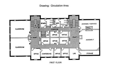
Circulation area is the floor area of verandah, passages, corridors, balconies, entrance hall, porches, staircase etc. which are used for movements of persons using the building, the circulating area of any floor shall comprise of the following:
  a) Verandah and balconies
 b) Passages and corridors.
 c) Entrance hall
  d) Staircase and mumties
 e) Shafts for lifts

CARPET AREA 
Carpet area of building is the useful area or liveable area or lettable area. This is the total floor area minus the circulation area (Verandahs, corridors, passages, lifts, entrance hall etc.) and many other non-useable areas as bath W.C., air conditioning room, etc. For office building carpet area is the lettable area or useable area, and for residential building carpet area is the liveable area and should exclude the kitchen, pantry, stores and entrance to other rooms which are not used for living purpose.


The carpet area of a building or any storey shall be the floor area excluding the following:
 1. Sanitary accommodation (bath & WC)
 2. Staircase and mumties
 3. Verandah

 4. Corridors and passages
 5. Kitchen and pantry
 6. Stores in domestic buildings
 7. Shafts for lifts
 8. Barsaties
 9. Garages
 10. Air conditioning ducts and
 11. Entrance hall and porches
 12. air conditioning plant room


The carpet area of an office building may be 60% to 75% of the plinth area of the building with a target of 75% The carpet area of residential building may be 50% to 65% of the plinth area of building with a target of 65% For a framed structure, multi-storeyed building, the area occupied by walls may be 5% to 10% of the plinth area (3% of external wall and 2% for internal walls) for ordinary building without the plinth area. Note: The plinth area, floor area, circulation area, carpet area etc. should be measured or taken separately of each storey or floor.
FLOOR AREA RATIO =
(total covered area of all floor /plot area)